

How Does Audi A3 Tire Pressure System Work
There are basically two kinds of Tire Pressure Monitoring Systems (TPMS) on the marketplace today. One kind (sensor-based) has sensors in each cycle that transmit an alert to the automobile if pressure is exterior the safe range. The other kind (wheelspeed-based) uses the ABS sensors to monitor the trends of wheel speeds with respect to each other. If one loses pressure, it will have a smaller diameter and a correspondingly higher rotation speed, so a alert can be triggered. There are pros and cons to each system. A complete discussion tin exist found here (PDF download from NHTSA/DOT).
Audi uses the wheelspeed-based system for the A3.
About a month ago, inspired by this thread on vwvortex, Ryan, Jim and I began discussing retrofitting TPMS to our A3s. I volunteered to exist the test example, and we ordered the required parts shortly after seeing this post by 'Theresias', who gave the part numbers and the programming changes that would be required. I'll reproduce the information here, only credit for initially describing it goes to Theresias. Cheers also to Jim (bassbiker) for his help, and especially for the apply of his VAG-COM system. Parts were sourced from vagparts.com (pricing to exist worked out shortly).
Before you first:
You must check to see if your ABS controller is compatible with this mod.
Versions claimed to work are:
- 1K0 907 379 K
- 1K0 907 379 Q
- 1K0 614 517 R
Parts List:
Here are the parts that are needed. Annotation that the switch is slightly different for the single-DIN nuance (e.k. with the Concert head unit of measurement) and the double-DIN dash (e.g. with the Symphony caput unit, or Navigation).
Switch for single-DIN dash: 8P0-927-121-5PR
Switch for double-DIN dash: 8P0-927-121-A-5PR
Needed for either switch -
- 1x Plug (maybe available in US): 4D0-971-636-A
- 2x Wires for TPMS switch plug (available in US): 000-979-009
- 1x Wire for ABS plug (bachelor in U.s.): 000-979-131
Programming -
- VAG-COM (CAN-capable version) from Ross-Tech
-OR-
- HPA VAD (with VAG module)(formerly known as ProDiag Hard disk from Shade Tree Software).
Generic items -
- xviii-gauge hookup wire, propose bluish, green, chocolate-brown, blackness
- Butt-splice crimp-on connectors for 18-22 gauge wire (non larger) (min. 5 needed)
- Circular lug connectors for eighteen-22 gauge wire (not larger) (min. 1 needed)
- Tap splice connectors for 18-22 guess wire (not larger) (min. ane needed)
- Wire stripping/crimping tool (but get ane, don't mess effectually with pliers)
- Add-a-excursion MINI (the smaller fuse size) for obtaining ability
- Heavy wire clotheshanger and 20-gauge steel 'safety wire', for angling through the firewall
- LOTS of normal and mini-size zip-ties.
- Electric tape (necessary), friction tape (optional)
- Various mitt tools, (8mm nutdriver, small apartment screwdriver, pliers, etc.)
Overview:
A pushbutton switch (Audi office) volition be installed in the nuance.
It will have 4 wire connections going to: +12V (black), Ground (brown), Fundamental Electronics module (blue), ABS module (green).
The ABS module is in the engine compartment, on the correct side of the firewall.
Once the physical parts are installed/hooked up, the feature needs to exist activated in the software coding for the ABS module
Procedure:
Remove the fuse cover on the left side of the dash carefully, then remove the ane silver commodities in there (attaching the lower nuance panel) using an 8mm nutdriver. Remove 2 identical bolts from the lower part of that panel in the driver's footwell. Pull the console straight towards the rear of the motorcar, abroad from the dash. Don't try to 'peel' it off by pulling from the bottom, it has to become straight dorsum pulling from most the acme.
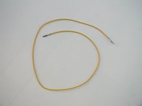
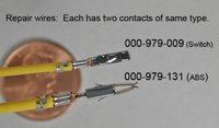
Yous volition need some 'repair wire' parts from Audi, which can be obtained from your parts department. They are a length of wire with a connector (the same one) on each stop. There are various connectors, for this project you volition demand part number 000-979-131, a female bract connector (one of those shown below), and ii of function number 000-979-009, a tiny female pin connector. You lot cut the wires in half to requite you two connectors/leads each which you will utilise at various points, and you can trim the wire downwards later equally needed.
Repair wire:
Comparison of the 2 sizes of the repair wires used for this projection, with office numbers.
Ability (switched +12V) was conveniently obtained by using a piggy-back fuse arrangement in the fuse-console. This is the 'MINI Add-A-Circuit' (FHM200BP) for the smaller fuse size, made by Littlefuse (standard fuse size packaging pictured beneath, but use the MINI one for this installation). I found them at a local auto parts store. You'll need a MINI one for this install. They hold two fuses each - the lower fuse is for the original circuit, and should be the amperage that was originally present in that slot. Just reuse the original fuse. The upper fuse is for the new excursion y'all're calculation, and should be the appropriate amperage for that. It is EXTREMELY Of import that you install these devices in the fusebox in the right direction - if you don't, the fuse winds up being downstream of the circuit, which is useless and potentially dangerous. You test this by plugging information technology into the fusebox and checking the voltage with and without a fuse in the upper position. If you still become power with the fuse non there, it'south backwards.... For the A3 fusebox, having the pigtails pointing down is the right orientation (but bank check information technology yourself to make sure).

Some of the factory wires for these circuits would be striped, but since I couldn't find striped wire I picked wire colours that correspond to the identifiable colours of the original colour code (e.k. for grey/green I used green). All wiring that I added is 18 gauge stranded hookup wire.

You will demand some common tools, and a wire strip/crimp tool (don't try to substitute pliers). In addition to a ringlet of electrical tape, you should also have a roll of friction tape (a cloth-like, viscous-on-both-sides, electrical tape). For the connections y'all will need some 18-22 gauge crimp-on butt splices, and 18-22 gauge tap splices:

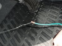
You take to get one wire through the firewall. Accept a stiff wire clotheshanger and make yourself a tool almost 60cm (2 feet) long with a large loop at one end for a handle. Poke the point of this wire through the grommet in the driver's footwell that is to the left of the clutch pedal, where in that location is already a wiring harness going through.
Proceed pushing information technology through, and information technology should appear somewhere around the battery box. Bend a very pocket-sized loop in the end of it, and attach something to it to pull back in. You can either pull the actual wire dorsum in, or you can have another footstep like I did (there is a logic to information technology, work with me hither...). Attach some 20gauge steel wire (eastward.grand. aviation 'condom wire') and pull information technology back through the firewall into the driver's footwell.

So attach the hookup wire to it and pull information technology through to the engine compartment:
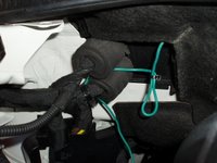
...and route information technology between the two soft pieces behind the battery box to protect it, and zip-tie it in place:


Now you can simply constrict information technology behind the insulation on the firewall and run it beyond to the right side of the engine. When you get to where the gasket curves, you will need to pull up the gasket to work with it for the moment:


I again routed information technology between the soft insulation , and left a fiddling excess behind the insulation. All of this is wrapped with friction record and is hidden behind the insulation, shown exposed here for example only:
This photo didn't turn out as well every bit I thought, sorry. There is a plastic cable chase on the side of the engine compartment just below where this wire is, and information technology covers office of the wiring harness going to the ABS plug. There are four clips belongings the cover on, I loosened three of them and ran the cable through the chase, and so snapped it back together. Shown hither held open then you can encounter the (green) wire running through.

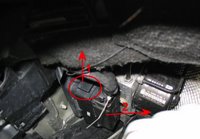
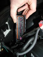
Now yous take to remove the ABS plug. At that place is a prune on top that pulls out (slides) UPWARDS ("1" in the photo). When you get it pulled out all the way, the plug pretty much falls off of the controller with no effort at all ("2" in the photo). Photo is of a MkV GTI, just is representative of the A3 for this purpose (image courtesy of squad-dezent.at):
With the ABS plug detached from the controller, it doesn't move very far. The cap on the back of the plug has to come off. This image is deceiving, because it's clipped on pretty securely. Y'all'll have to loosen the two clips at the dorsum of the plug first (near the sliding clip), then the ones at the other finish. Utilize a short-handled flat screwdriver. Sorry, no photo of this process:

Locate the right pin location on the face up of the ABS plug, the part that plugs into the ABS controller:
For most manual transmission A3s and early DSG A3s without the 'Colina Hold' role, this should be Pin 27.Virtually new DSG-equipped A3s have the 'Hill Hold' part, and volition have a Red/White wire already in pivot number 27. For those cars, the right location is Pin 41. Do not disturb whatever already-existing wire in Pin 27 on those cars.
The middle row goes (from sliding clip stop to the other finish):
17 eighteen 19 20 21 22 23 24 25 26 27 28 29 thirty 31.
The bottom row goes (from sliding clip terminate to the other end):
32 (wide pin on the outside) 33 34 35 36 37 38 39 xl 41 42 43 44 45 46 47 (wide pin on the outside)

View of the plug and the socket, for reference:

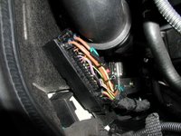
Look at the back side of the plug, where all the wires are, and discover the pin number marking at the cease of the heart (or bottom, as advisable) row and count backwards from at that place. There should be no wire in the plug at that position originally. This is where we'll install one of the repair wire clips.
Indicating the location of Pin 27 on the face of the plug:
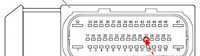
Indicating the location of Pin 41 on the face of the plug:

Almost all of the Audi plugs have to be 'unlocked' earlier you lot tin insert a new pivot, similar we're going to do. On this plug, wait for the majestic plastic. You will see a '+" shaped royal piece at 1 end, and a slot in the regal at the other end. This photo shows a screwdriver in the slot. Use the screwdriver to slide the majestic plastic very slightly (about 0.5mm) towards the sliding-prune end of the plug until you hear/feel a 'click':
Use a nail in a pair of locking pliers to excerpt the rubber plug from position 27 (or 41, as appropriate) on the back of the plug, then use the aforementioned nail to pierce the safe plug lengthwise to accomodate the wire.

Have the repair wire 000-979-131 and cutting in in half to get a connector with a atomic number 82 on it. Insert the atomic number 82 through the rubber plug in the orientation shown here (larger connector shown for instance just):

Insert the repair wire connector into the position 27 (or 41, as appropriate) of the ABS plug from the back side, until information technology clicks in firmly. It only fits in one way - y'all can figure information technology out. If you can't get information technology all the mode in until it clicks, brand sure you unlocked the regal part as described above. When finished, tt should look from the front just like the others in the plug, and you should seat the rubber plug into the hole behind it so that it looks like the other wires (make sure yous slide the purple function the other way to 'lock' it again).
Use a barrel-splice to join the wire you lot ran previously to the cease of the repair wire you lot just installed in the plug. You'll demand to practise some trimming, and the splice should look like this:

Seal the butt-splice with electrical record, and use small zip-ties to secure it to the heavy brown basis wires in the plug. In this photo, yous tin can run across how the green wire which was run down to the ABS plug was cypher-tied securely to the harness on the way down:
Wrap the wiring harness going to the ABS plug with friction tape which volition cover the new wire and zip-ties and will mimic the stock 'wrapped' appearance of the harness in that surface area.
Installation is the opposite of removal: Make sure the regal plastic on the plug is in the locked position. Reinstall the cap on the back. Pull out the sliding clip, position the plug on the controller, and push the clip in to lock the plug in place securely. Finished production shown here:

Nosotros're washed outside. At present we move on to the interior portion.
Take two repair wires (part number 000-979-009) and cutting them in one-half to obtain four pins with leads. Insert the leads into the 4 corners (pins 1, 3, 4, vi) of the plug (part number 4D0-971-636-A), and lable them:
- Pivot ane: (BLUE) Primal Electronics
- Pivot 3: (Brownish) Basis
- Pin four: (BLACK) +12v
- Pin 6: (GREEN) ABS

Make up the rest of your harness by bundling (with nil-ties...) the green wire coming through the firewall from the ABS controller with the dark-brown, blackness and blueish wires. You'll accept to exercise judgement about routing under the dash and leaving plenty actress to work with. Plain, read and understand all of these instructions before starting, and map out where everything is going to go before you go started. In any instance, you will get these four wires up and through the switch position in the centre of the dash. Trim the backlog, and attach the corresponding wires to the leads from the plug with the butt-splices (you did label them like I said, correct?):

Plug in the switch, and snap information technology into the nuance:

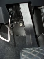
Connecting to the Fundamental Electronics control module isn't hard, merely abrasive because it's in a tight spot. It's upwards under the dash, above and to the left of the clutch pedal.
Beginning, permit's get oriented to what is where on the module.
The controller should have a lable on it of 'Bordnetzsteuergerat'.
The side facing downwards has infinite for viii plugs on it. A, B, C, D are on the first row, and Due east, F, G, H are on the second row. In the photo below, identify plug B (black, top row, 1 in from the left).
In the photograph, find the red plastic bar running side-to-side between the rows of plugs. You lot must slide it to unlock the plugs, otherwise the plugs do non come out. After you unlock it, you can release the tab on the plug to take it out.
You're going to connect to Pivot 12 on Plug B. There are two possibilities - either there is a wire already in the plug in that postition, or there isn't. If there is (as was the example in my car), simply use a tap splice to connect to it. The factory wire for that position would be blue&grey, our wire is blue. The finished connection is shown in the photo.
(If in that location is no wire already in that plug position, you will need to employ the other half of the 000-979-131repair wire left over from the ABS plug connection and install it Plug B position 12. In that location is a imperial locking piece on the plug that will have to be unlocked earlier/relocked after installing the connector. This note is likely not needed, but is included for completeness.)
Once the blue wire is connected to position 12, make sure the plug is firmly clicked into the Central Electronics module and the scarlet bar is dorsum in the 'locked' position:
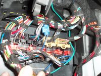
The last bit of the physical installation is power. Our black wire goes to the Add-A-Circuit MINI, which I placed in fuse position 8 with a 5A fuse (the other ii Add-A-Circuit pieces in the photograph are for my bluetooth handsfree kit).

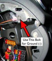
Our brown footing wire should have a round lug connector crimped on to it, and should be attached to this bolt. Sandwich information technology between the nuance cover and the metal support and supervene upon the bolt, for best electric contact.
The nuance can now be closed upward. The physical installation is finished, all that remains is the coding.
Coding the module to make this work:
A VAG-COM system was used to enable the TPMS functions. In VAG-COM, go into the ABS module and edit the coding. You should decrease 16384 from the original coding. For example, if your original coding was 0021122 like mine was, subtracting 16384 from it gives a code of 0004738. Save this new coding and get out. The TPMS installation is now consummate.
Check that your tire pressures are all right.
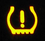
With the car running, printing and hold the 'Prepare' button. The TPMS symbol (see below) will illuminate, and so go out. When it goes out, release the push button and you lot will hear a beep (like the depression-fuel beep). The system is at present reset and gear up to learn your wheelspeed values.

The following is from Theresias' original post:
After connecting the button, check if it'due south working or non, you should utilize VAG-COM and ABS Measuring Block 018 Field ane.How information technology Works:
Outset off, the new button only resets the TPMS learned values, subsequently that it needs some driving distance to relearn these values. The learned values are adapted in several steps (speed ranges), each step (range) is devided into 2 thresholds in ii stages (powered and rolling). You can check this using VAG-COM and read measuring block 031 in your ABS control module.
031,0,Tire Pressure Monitoring (TPMS) IV
; 0 = Nothing Learned
; 1 = Only 1st Threshold powered
; 2 = Only 2nd Threshold powered
; 3 = But 1st Threshold rolling
; four = But 2nd Threshold rolling
; v = 1st Threshold powered and rolling
; half-dozen = 1st Threshold powered and 2nd Threshold rolling
; seven = 2d Threshold powered and 1st Threshold rolling
; eight = 2nd Threshold powered and rolling (Optimal)
031,1,Speed Ranges I
; 5?xxx = Speed Range ane ( xv - 70 km/h)
; 5x?xx = Speed Range 2 ( 70 - 100 km/h)
; 5xx?x = Speed Range 3 (100 - 130 km/h)
; 5xxx? = Speed Range 4 (130 - 160 km/h)
031,2,Speed Ranges Ii
; v?thirty = Speed Range 5 (160 - 190 km/h)
; 5x?xx = Speed Range six (190 - 220 km/h)
; 5xx?x = Speed Range 7 (220 - 250 km/h)
031,three,Bend/Wheel,Recognition
; 5?x00 = Bend Recognition (0 = No Curve / 1 = Left or Correct Curve learned / ii = Complete Curve learned)
; 5x?00 = Wheel Recognition (0 = inactive / one = activ)Optimal would be:
031 Field 1 = 58888
031 Field 2 = 58880
031 Field three = 52100
As well, considering I know somebody is going to come across this....
Question: What is this item for? Byte 01 Bit 7 Tire Pressure Monitoring (Address 65) in the Can Gateway. Is this related to this system, or a unlike one?Answer: It is unrelated, get out it alone.
This was the get-go complete A3 TPMS installation in the US.
Having done this mod, I now have some ideas virtually how to pre-make the wiring harness differently, already cut to length with more soldered connections before installing in the machine. If I become the chance to do this to someone else'south motorcar, I'll update this posting with any improvements to the process.
DOWNLOAD HERE
How Does Audi A3 Tire Pressure System Work
Posted by: sanbornfreand.blogspot.com
0 Response to "How Does Audi A3 Tire Pressure System Work"
Post a Comment